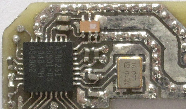
atben only has the transceiver and the balun. The markings on
both face towards the crystal and the antenna:

The corner next to pin 1 of the transceiver is marked with a small dot.
The picture above also shows the orientation of the text printed on
the package. The balun is marked with a square between pins 1 and 6.
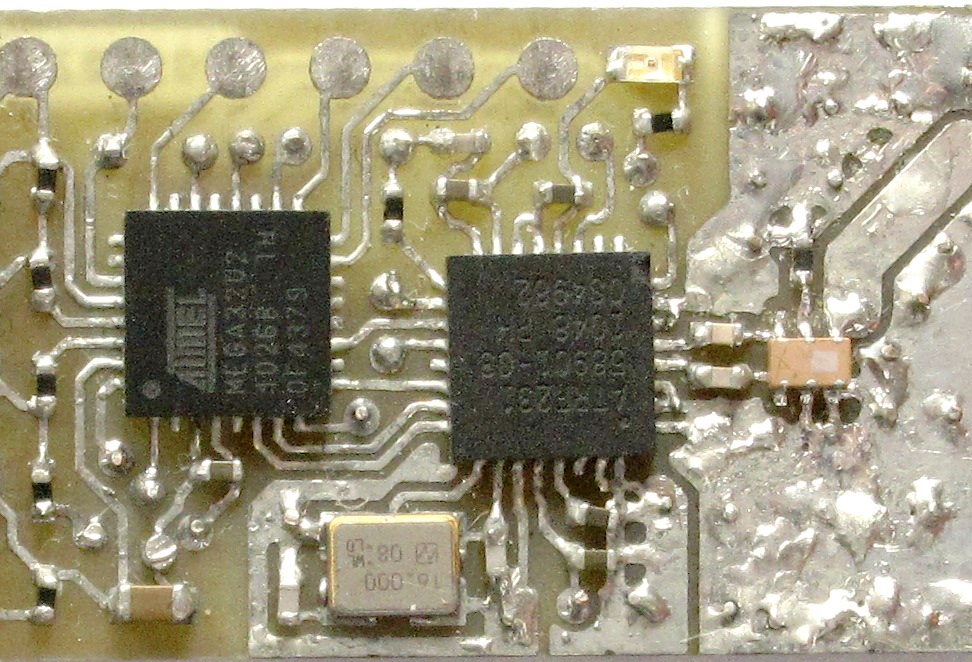
In atusb, the marking on the transceiver is on the corner between
the crystal and the antenna. The marking on the balun faces towards the
antenna. The microcontroller's "top" side faces towards the USB connector.

It is difficult to determine the LED's orientation by visual inspection.
An efficient approach is to touch the LED's terminals with the probes
of a multimeter set to measure resistance. The small current used for
the measurement will light the LED.
The transceiver has three voltage domains:
- The supply and I/O voltage, which is nominally 3.3 V in
atben and atusb,
- the digital (core) supply, which is nominally 1.8 V, and
- the analog (RF) supply, which is nominally 1.8 V.
On atusb, there is also the USB voltage domain at nominally 5.0 V.
Voltages should be tested in the following order: USB, then I/O, then
digital, and finally analog. The table below gives the permissible
ranges. Any voltages outside these ranges indicate a problem.
| Domain | Nominal | Minimum | Maximum
|
|---|
| USB | 5.0 V | 4.5 V | 5.25 V
|
| I/O | 3.3 V | 3.0 V | 3.6 V
|
| Digital | 1.8 V | 1.7 V | 1.9 V
|
| Analog | 1.8 V | 1.7 V | 1.9 V
|
The measurements should be performed with a digital multimeter.
The transceiver's analog and digital supplies (1.8 V) are only
activated when sending or receiving.
To enable all voltage domains, put the transceiver in receive mode:
atrf-txrx
or
atrf-txrx -d net:ben
Exit with Ctrl-C.
To produce periodic transmissions in addition to enabling all voltage
domains, use
atrf-txrx -p 3 -E 0
or
atrf-txrx -d net:ben -p 3 -E 0
Again, exit with Ctrl-C. Note that the transmissions may disturb nearby
equipment operating in the 2.4 GHz band, such as 802.11 networks. This
can be prevented by shorting the antenna to ground.
In case the board does not accept commands, only the USB and I/O voltage
can be checked. If they are correct, proceed with checking the clock.
The supply voltages on atben can be measured at the terminals of
components as shown in this table:
| Domain | Voltage | Component
|
|---|
| I/O | 3.3 V | C3, C6
|
| Digital | 1.8 V | C5
|
| Analog | 1.8 V | C4
|
Ground can be accessed at the cover of the crystal.
Note that the fiducials, while looking like test points,
are not connected to anything.
This image shows the location of the measurement points:
 The supply voltages on atusb can be measured at the terminals of
components as shown in this table:
The supply voltages on atusb can be measured at the terminals of
components as shown in this table:
| Domain | Voltage | Component
|
|---|
| USB | 5.0 V | C1
|
| I/O | 3.3 V | C2, C10, C13
|
| Digital | 1.8 V | C12
|
| Analog | 1.8 V | C11
|
Ground can be accessed at the cover of the crystal, at the shield of the
USB connector, or at the test point P11.
Note that the fiducials are not connected to anything.
This image shows the location of the measurement points:
 The precision of the crystal oscillator is crucial for
operation. Anomalies are easy to detect with even a low-cost oscilloscope.
This can pinpoint specific problems and help to select further analysis steps.
The crystal used in atben and atusb has a nominal tolerance
of +/− 15 ppm at 22-28 C. Low-cost oscilloscopes typically have a timing
accuracy of
+/− 100 ppm, which means that only major excursions can be detected by
measuring the clock output with such an instrument. Full-speed USB only
requires an accuracy of +/− 2500 ppm.
We can therefore consider all results within a range of +/− 1000 ppm as
sufficient for an initial assessment, and perform more precise measurements
by other means. This
applies to atben as well as to atusb.
The precision of the crystal oscillator is crucial for
operation. Anomalies are easy to detect with even a low-cost oscilloscope.
This can pinpoint specific problems and help to select further analysis steps.
The crystal used in atben and atusb has a nominal tolerance
of +/− 15 ppm at 22-28 C. Low-cost oscilloscopes typically have a timing
accuracy of
+/− 100 ppm, which means that only major excursions can be detected by
measuring the clock output with such an instrument. Full-speed USB only
requires an accuracy of +/− 2500 ppm.
We can therefore consider all results within a range of +/− 1000 ppm as
sufficient for an initial assessment, and perform more precise measurements
by other means. This
applies to atben as well as to atusb.
IEEE 802.15.4 requires the transceiver frequency to be accurate
within +/− 40 ppm.
atben normally does not output a clock signal. A 1 MHz clock
can be enabled with the following command:
atrf-txrx -d net:ben -C 1
This configures atben as a promiscuous receiver. The reception
of any IEEE 802.15.4 frame or pressing Ctrl-C will terminate the command.
The clock signal (CLKM) is available on the test pad shown on the image
on the left, and it should look roughly as shown in the screen shot on
the right:

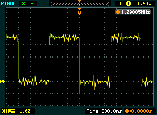
| Clock | Action
|
|---|
| 0 Hz | Check voltages; check that the clock is enabled;
check for shorts around crystal; check connectivity of crystal
|
| 0.999-1.001 MHz, ~3.3 Vpp | Perform precision measurement with
atrf-xtal
|
| Other | Check voltages; check for contamination around crystal
|
The transceiver provides the clock for the microcontroller in atusb.
A clock signal is therefore always available. Immediately after reset,
the transceiver generates a 1 MHz clock. When the microcontroller comes out
of reset, it raises the transceiver's clock output to 8 MHz and then
enables USB.
The clock signal is available at the terminals of several components,
either as the direct output from the transceiver (CLKM) or after passing
a low-pass filter (CLK):

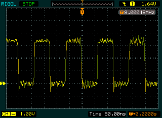
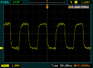
The left screen shot shows the clock (CLKM) before the low-pass filter
while the right screen shows the clock (CLK) after the the low-pass
filter.
| Clock | Action
|
|---|
| 0 Hz | Check voltages; check for shorts around crystal; check
connectivity of crystal
|
| 0.999-1.001 MHz, ~3.3 Vpp | Check presence of firmware; check for
shorts on SPI signals; check connectivity of SPI signals
|
| 7.992-8.008 MHz, ~3.3 Vpp | Perform precision measurement with
atrf-xtal (@@@)
|
| Other | Check voltages; check for contamination around crystal
|
Note that, if testing a board into which no boot loader has been flashed
yet, the clock frequency should be 1 MHz. If an unsuccessful attempt has
been made to flash the boot loader, the frequency may be 1 MHz or 8 MHz,
depending on how much code was successfully flashed.
The clock frequency of atben can be measured with an accuracy
of about +/− 100 ppm using the program atrf-xtal. atrf-xtal
runs directly on the Ben and measures the duration of packet transmissions.
The transmission time depends on the bit clock which is in turn derived
from the oscillator.
ben# atrf-xtal 100
The number reported is the number of poll loops the CPU counted. This
value should be compared to a reference count obtained with a known to
be good atben board on the same Ben at a comparable temperature.
| Difference | Action
|
|---|
| < +/− 50 ppm | Correct operation
|
| < −80 ppm | Check soldering of capacitors;
check for contamination around crystal
|
| > +120 ppm | idem
|
| Other | Deviation can be compensated by adjusting trim value
|
The clock frequency of atusb can be measured with an accuracy
of about +/− 1 ppm relative to the PC's NTP-disciplined clock.
pc# atrf-xtal 10000
This measurement runs for 10−60 seconds, depending on system load.
Note that, in order to reach such a high precision, it is imperative
that the PC clock be disciplined by NTP.
| Difference | Action
|
|---|
| < +/− 30 ppm | Correct operation
|
| Other | See the atben section above
|